


Some Hardware Modifications of the Nokia dBox
Introduction
This article describes some hardware extension that I felt "was necessary" to my Nokia dBox. First of all, although the box is fairly well equipped with video outputs (see this article), I wanted outputs to be simultaneously connected (although they could still not be simultaneously used) to YUV-inputs, SVideo-inputs, and RGB-inputs. I wanted to see if the mysterious "v3"-output worked. Also some other minor modifications are described herein.
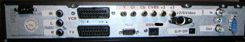
This is the back plate of the modified dBox:
This article uses terminology and facts from the previous article. A reasonable understanding of electronics is assumed.
Some more photos are collected here. 
Additional Video Outputs
Although the dBox is in the position (see this background article and this improved controld) I wanted to be able to connect YUV-cables (preferably fitted with RCA jack) simultaneously with the RGB-connection. An S-Video Hosiden connector would be nice too. Unfortunately, "snarfing a video signal" is not as easy as making an additional analog audio output where you can just connect them in parallel. It turned out that all the video signal outputs where using the same emitter follower as output step, see the following figure.
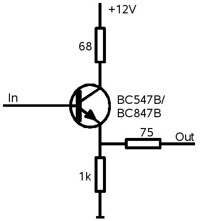
The working of an emitter follower is described in every elementary electronics textbook. We just remark that the voltage of "Out" follows "In" very closely, while loading the input very little.
In all cases, "In" is connected to pins of the AV-Switch, and "Out" to different pins on the Scart connectors. The transistor BC547B is the discrete component, while BC847B is the SMD version, used in the Nokia. I duplicated this circuit for all extra video outputs desired, taking the "In" signal from the appropriate pin of the AV-Switch, and feeding the output to an RCA- (or Hosiden) jack. In this way, I have made separate RCA jacks for the four output pins (labeled Y, Cb, Cr, and CVBS respectively). These correspond to the "v1" video output channel, also connected to the TV-Scart. From the "v2" video output channel (connected to the VCR-Scart), both signals are taken to a Hosiden connector. The CVBS-Signal is taken to an RCA-jack. Finally, the mysterious "v3" video output was taken from pin 27 on the CXA2092.
Holes were drilled in the back plate and appropriate RCA and Hosiden jacks were mounted. The components were essentially soldered to the output jacks, with cables to connect the base of the transistor to the AV-Switch's pins. It turns out that 75 ohm resistors are slightly hard to get by; Conrad sells them, but only in quantities of 100 (Order number 408948 - 62).
The outcome of this modification is quite pleasing. In particular, I not need to use my Scart-Switcher as a signal splitter.
Inhibiting Wake-Up from SCART-Inputs
As described in the previous article, it may be desirable not to let active-going pin8 on the VCR-Scart wake up the dBox. For this, we used exactly the same circuit, but where "+12V" has to be taken from a point that is 0V during deep standby. The connection for pin8 on the VCR-Scart was cut, "In" connected to pin8 of the VCR-Scart, and "Out" to the PCB, where pin8 had gone previously. It turned out that the most difficult part was to find an appropriate 12/0V supply. For this, I used the signal denoted +12V_OPB on the circuit diagram, available just under the modem connector, see the green wire on photos.
The emitter follower is shown here:
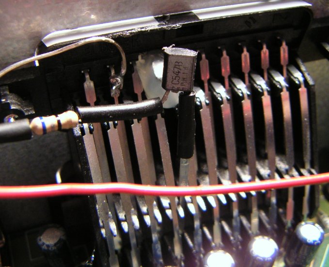
It turns out that a Scart-connector with one pin cut on the inside is mechanically prone to problems. For this, I fixed the pin with hot glue, as can be seen from the picture.
Miscellaneous
The power cable was a non-detachable cable, equipped with a Euro plug. A detachable cable has some advantages, when swapping my Nokia dBox and my Sagem, or when (occasionally) the need for power cycling occurs. It was also my intention to replace the fairly useless modem with a second RS232 output. At the time of this writing, this is unfortunately not yet working. (In Internet available pin-outs for the modem connector appear not quite accurate.)
Finally, as can be seen from the photographs, the different connectors were labeled in a more readable fashion than in original.